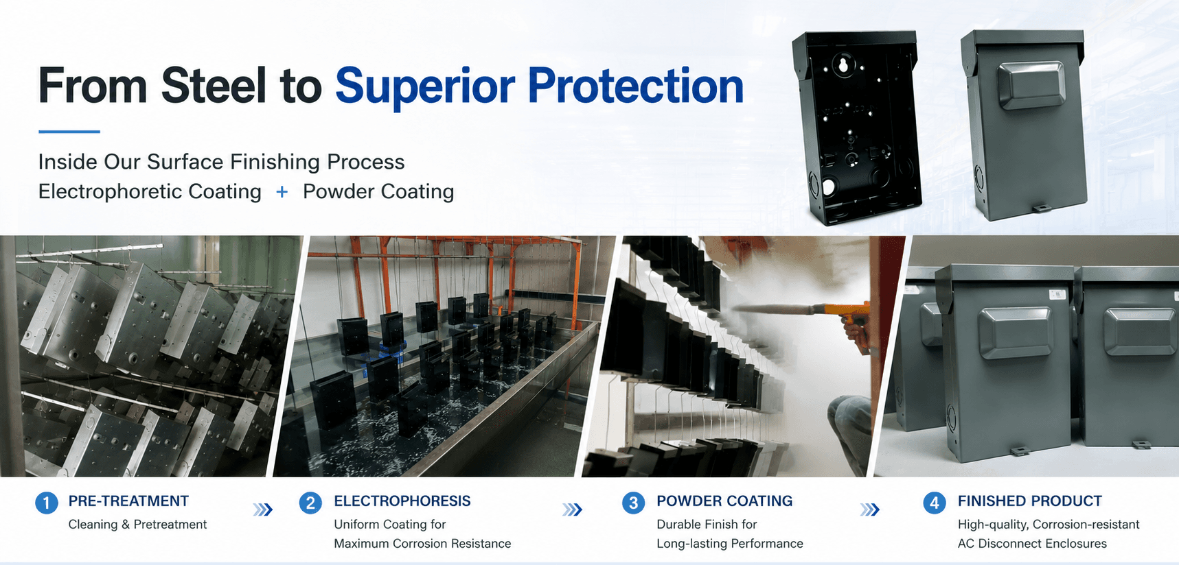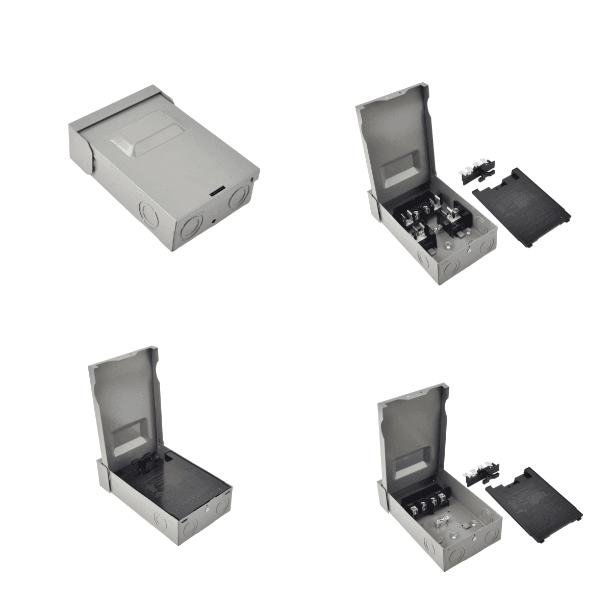
Why We Performed This Test
Powder coating is widely used on outdoor electrical enclosures because it provides a durable surface finish and practical environmental protection. However, the corrosion resistance of a finished steel electrical enclosure depends on more than the visible outer coating.
Surface preparation, edge coverage, punched openings, screw holes, coating thickness and the use of an additional electrophoretic coating layer can all influence how corrosion begins and develops in a protective coating system.
To better understand the difference between the two coating systems, Daheng Electric conducted a controlled side-by-side comparison using four steel enclosure samples exposed in the same neutral salt spray test chamber at the same time.
The Main Question
Does an electrophoretic coating layer beneath the powder coating provide additional corrosion protection compared with powder coating alone?
Four Samples, Two Coating Systems
Four steel electrical enclosure samples were used in the comparison. The samples were divided into two groups, with two samples in each group.
Group A
Powder Coating Only
Two powder-coated steel electrical enclosure samples finished with the standard powder coating process without an electrophoretic coating base layer.
Group B
Electrophoretic Coating + Powder Coating
Two steel electrical enclosure samples treated through the electrophoretic coating process before the final powder coating process.
Test Conditions
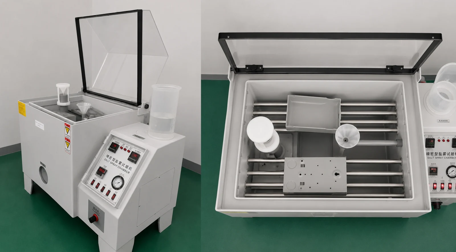
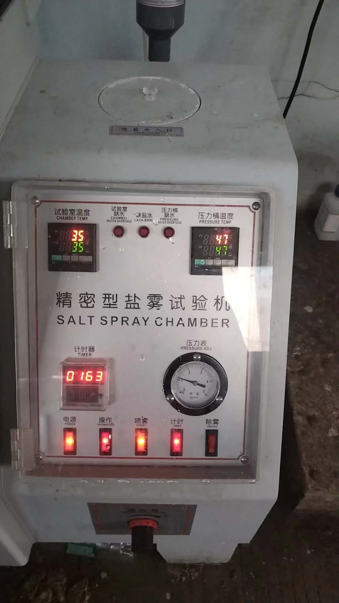
All four samples were placed in the same chamber and exposed simultaneously to reduce variations caused by equipment conditions, test duration and salt spray concentration during the accelerated corrosion test.
| Test Item | Test Condition |
|---|---|
| Test Method | Neutral salt spray exposure |
| Reference Method | ASTM B117-style test conditions |
| Salt Solution | Approximately 5% sodium chloride |
| Chamber Temperature | Approximately 35 degrees C |
| Number of Samples | 4 |
| Powder-Coating-Only Samples | 2 |
| Electrophoretic + Powder Samples | 2 |
| Intermediate Inspection | 163 hours |
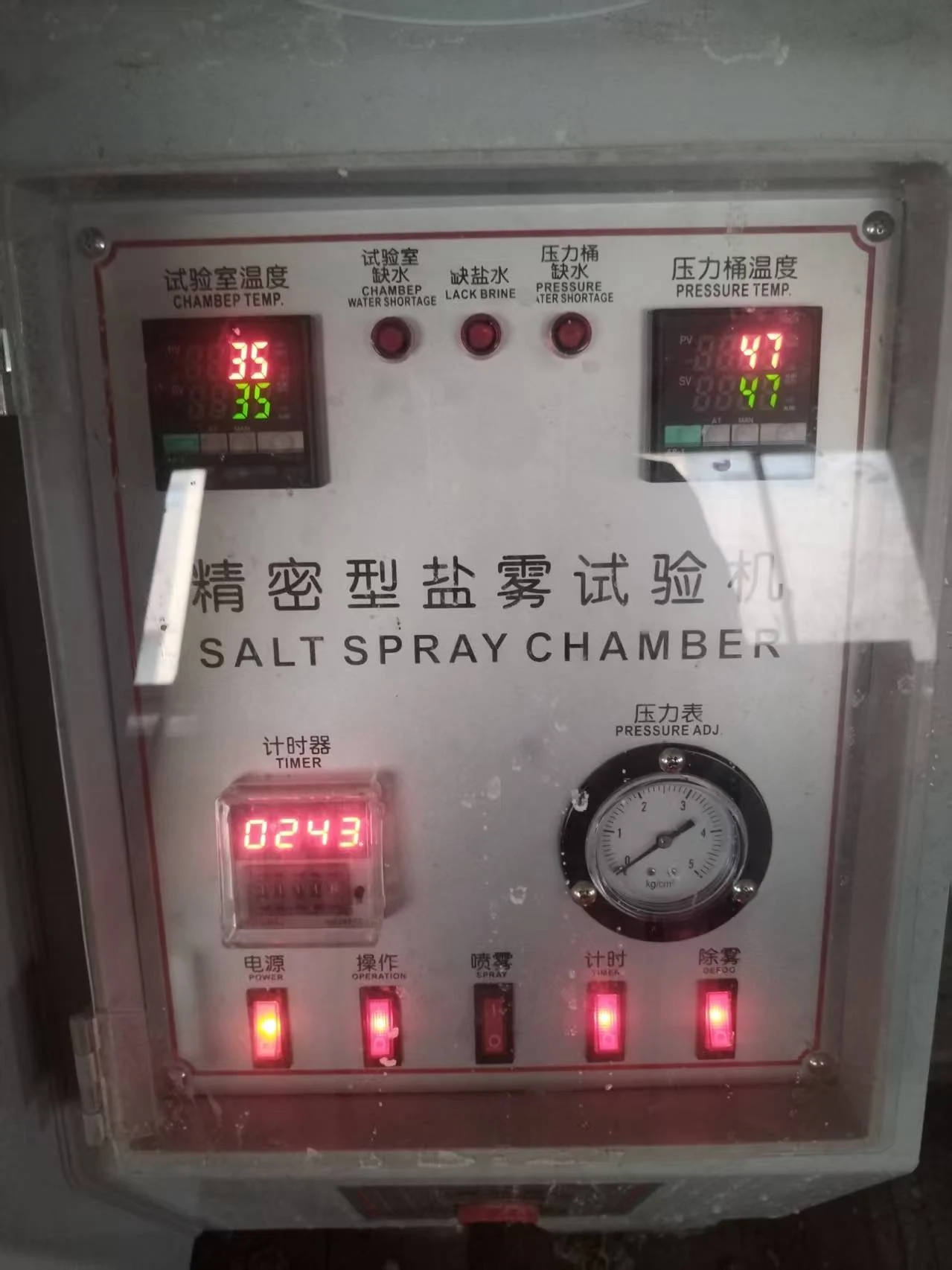
| Final Inspection | 243 hours |
The test was conducted in Daheng Electric's internal testing facility. The purpose was to compare the relative performance of the two coating systems under the same internal test conditions.
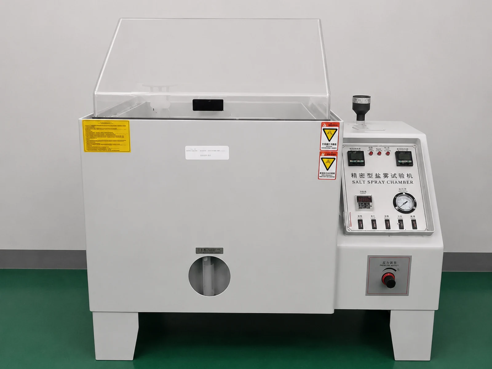
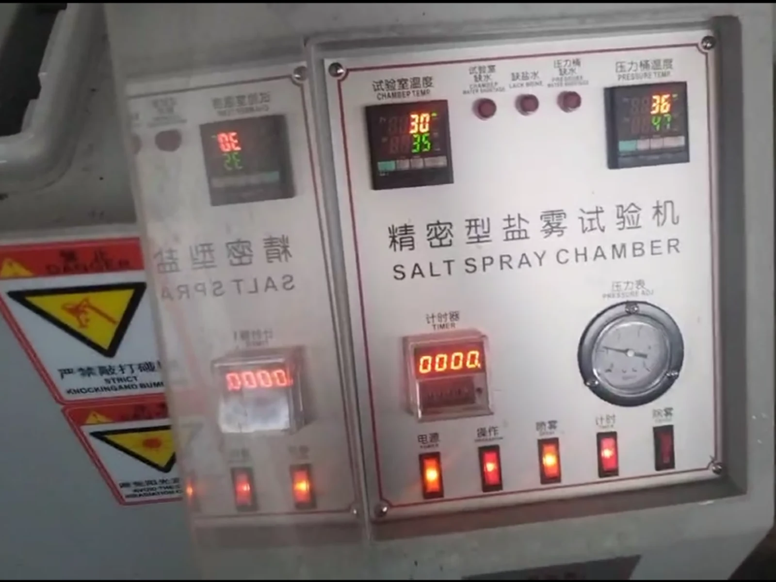
Figure 2. Test chamber and equipment status at the beginning of the comparison.
Condition Before Testing
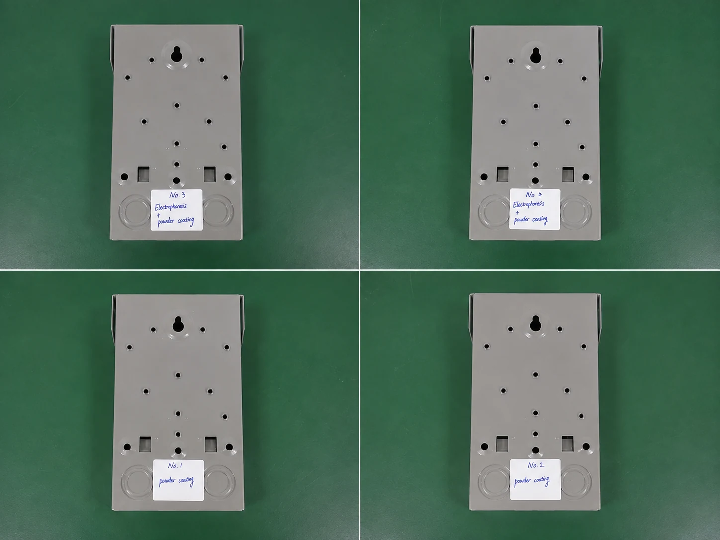
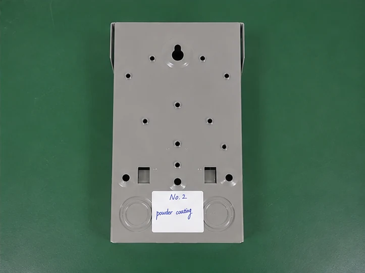
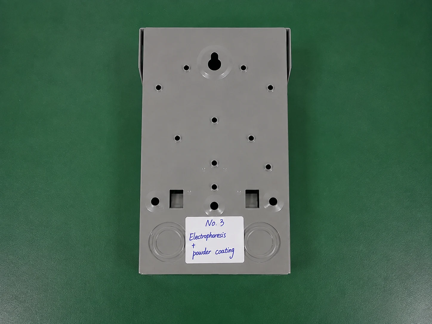
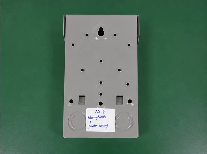
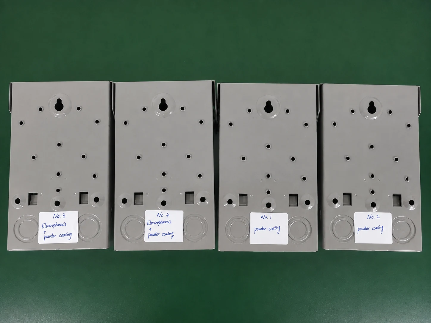
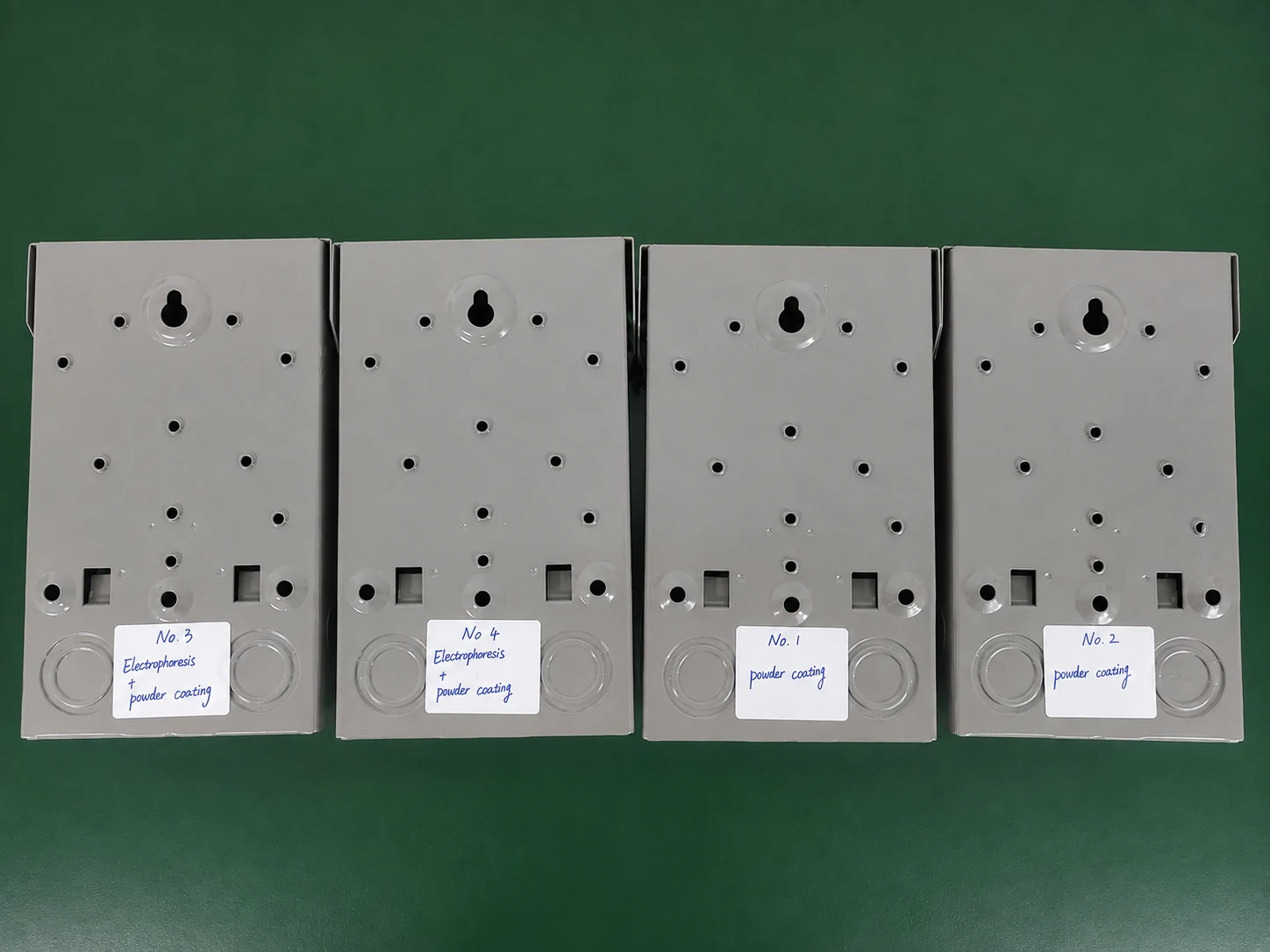
Before entering the salt spray chamber, all four samples were visually inspected and photographed. The initial images provide a reference for evaluating later changes in the coating surface, edges, punched openings, screw holes and other exposed areas that can affect steel enclosure durability.
- Coating surface condition recorded
- Edges and corners inspected
- Screw holes inspected
- Knockout areas inspected
- Sample identification confirmed
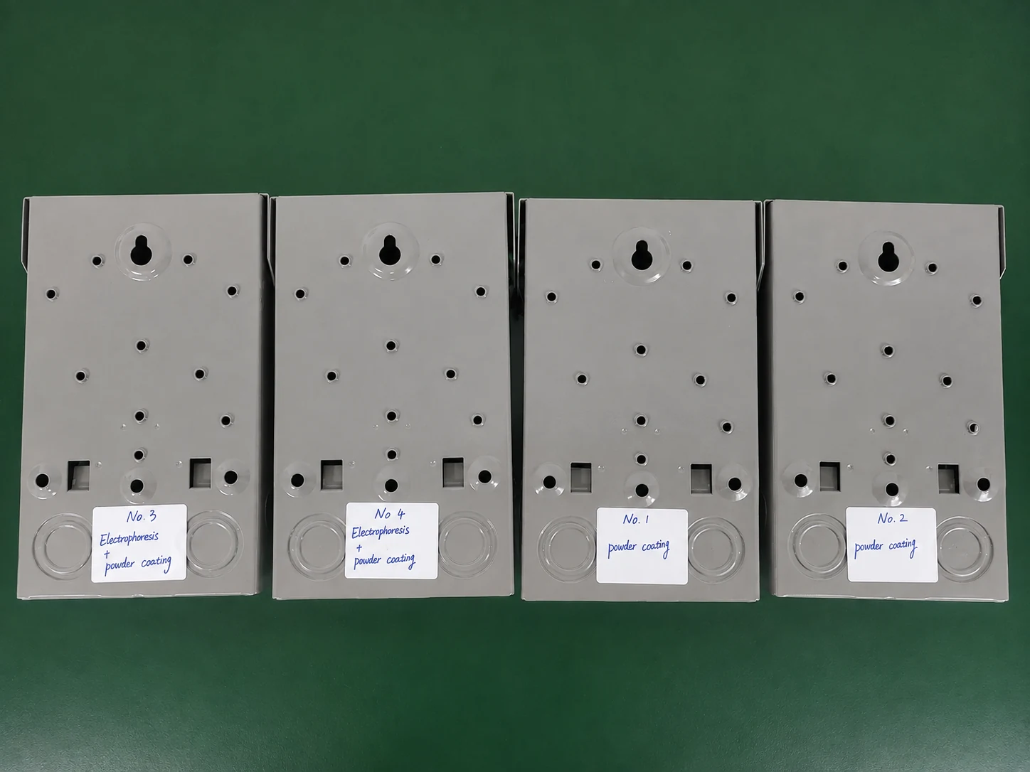
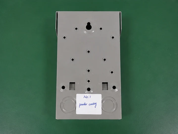
Sample A1
Powder Coating Only
Sample A2
Powder Coating Only
Sample B1
Electrophoretic Coating + Powder Coating
Sample B2
Electrophoretic Coating + Powder Coating
Figure 3. Initial condition of the four samples before salt spray exposure.
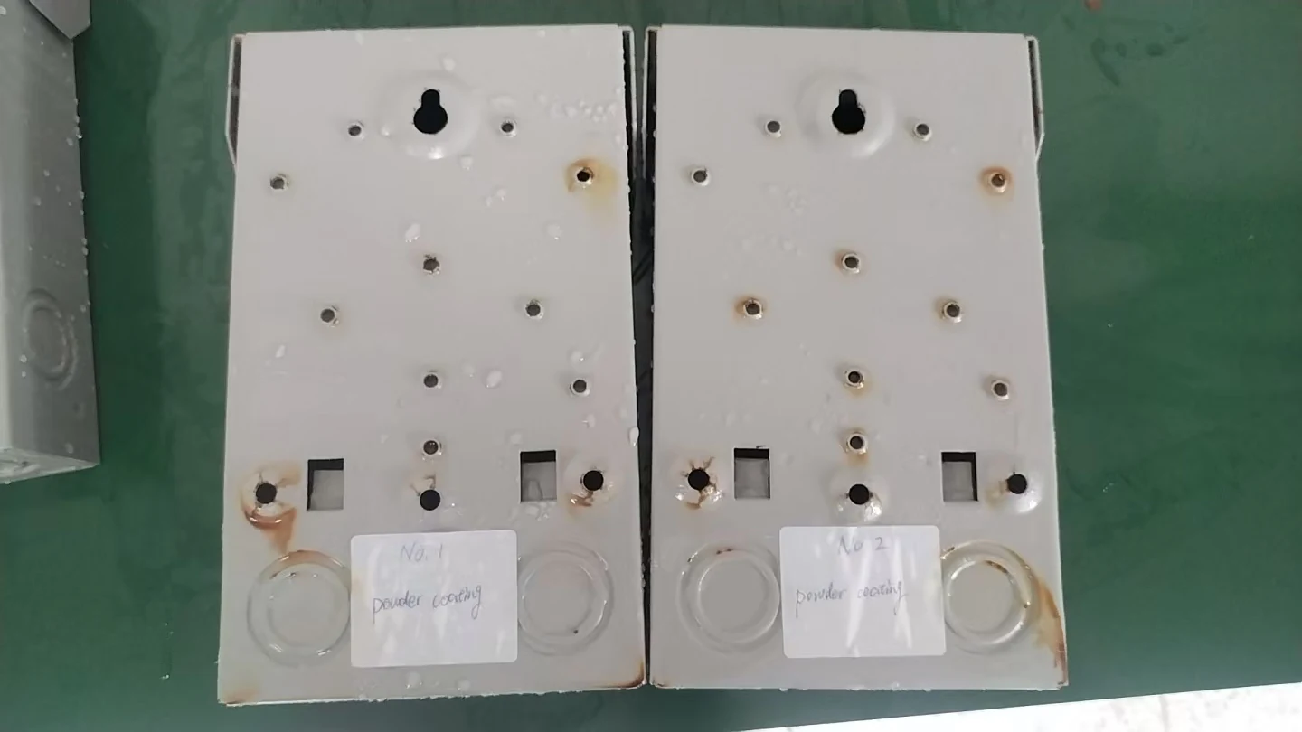
Intermediate Inspection at 163 Hours
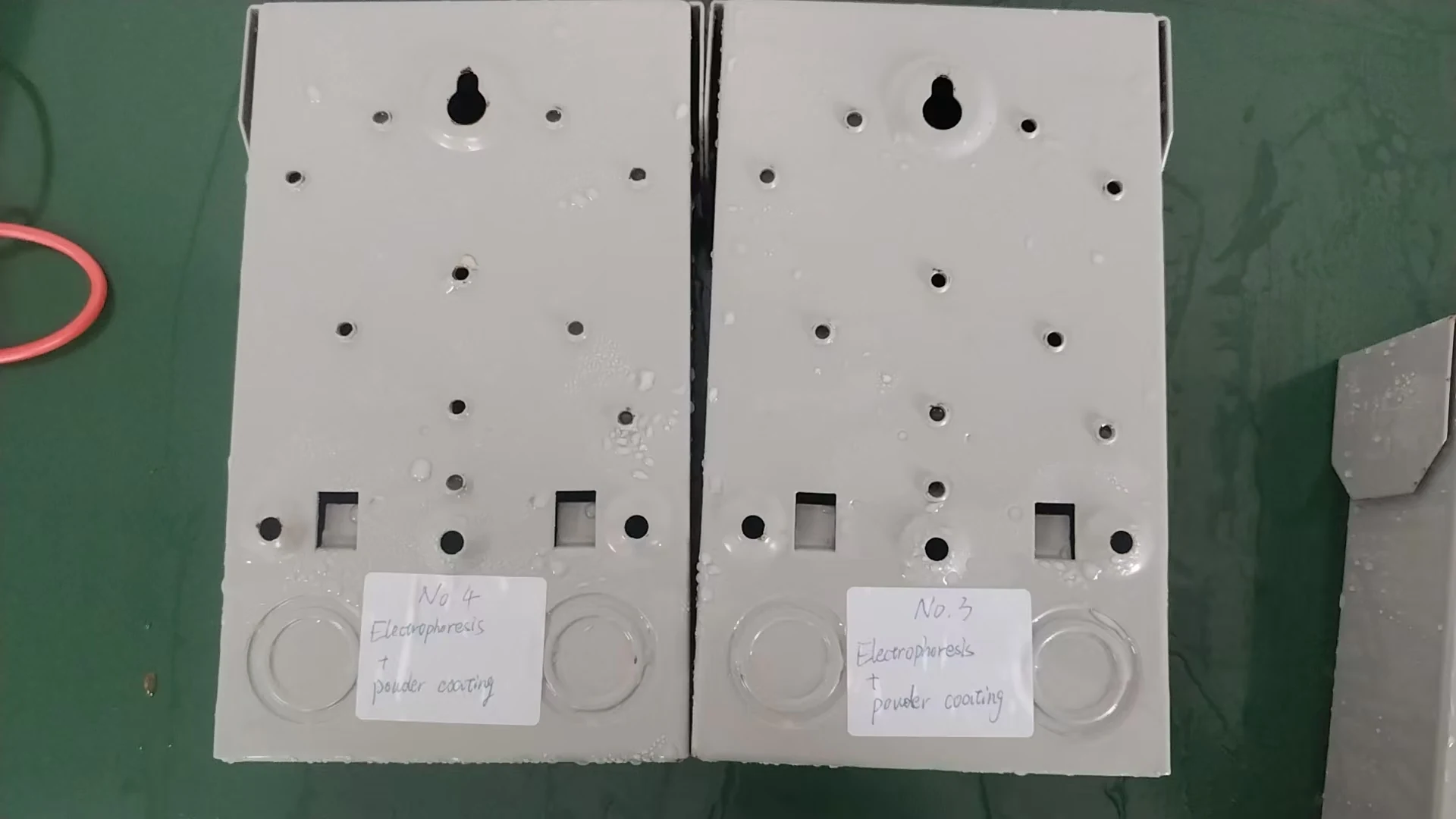
The first detailed inspection was performed after 163 hours of continuous salt spray exposure. At this stage, the powder-coated steel samples were photographed to document any visible changes in coating condition and the early development of corrosion.
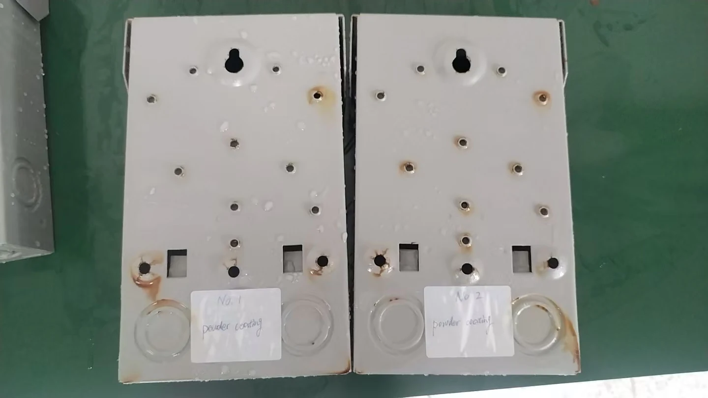
Samples A1 / A2 - Powder Coating Only
Sample A1 and Sample A2
Powder Coating Only
Observation
Observation details will be added after final image review.
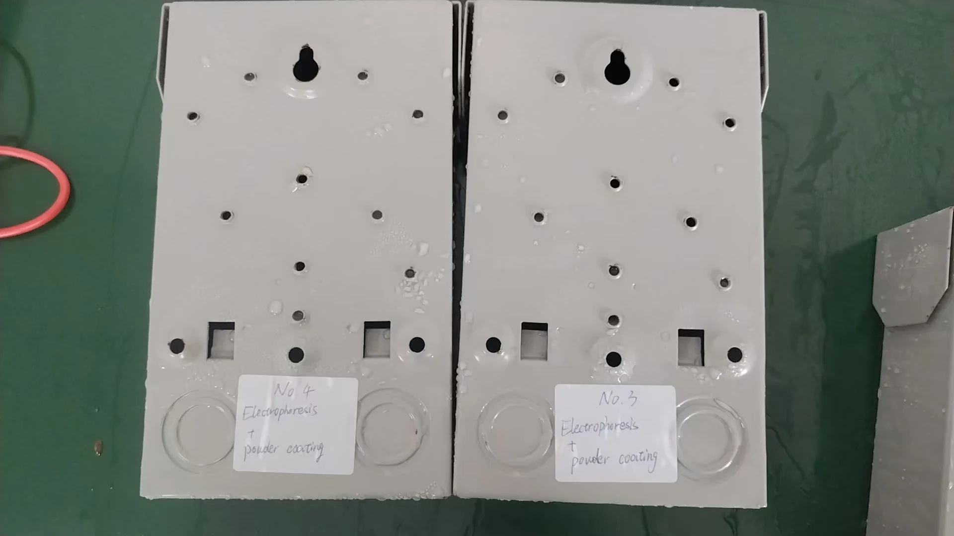
Samples B1 / B2 - Electrophoretic Coating + Powder Coating
Sample B1 and Sample B2
Electrophoretic Coating + Powder Coating
Observation
Observation details will be added after final image review.
Inspection Focus
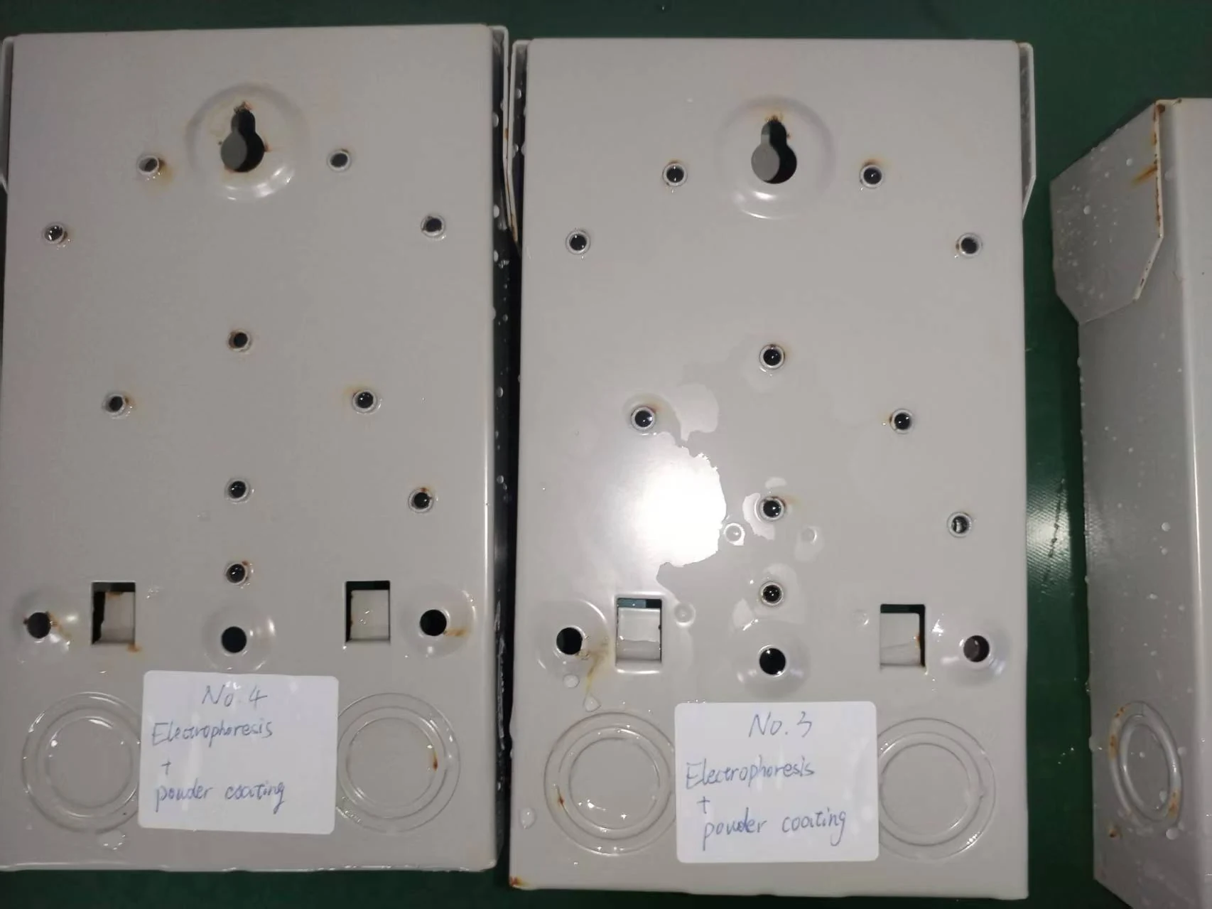
The inspection focused on visible rust initiation, edge corrosion, screw holes, punched openings, coating blistering, discoloration and corrosion spread.
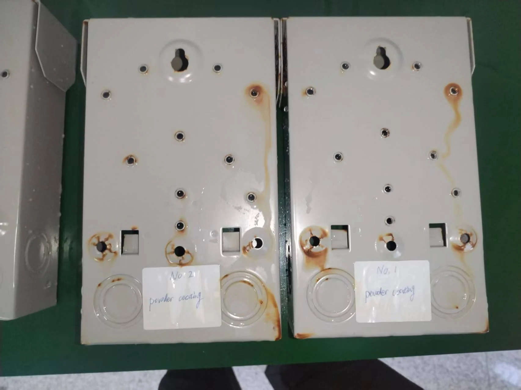
Final Inspection at 243 Hours
The final documented inspection was completed after 243 hours of salt spray exposure. The same inspection points used at 163 hours were reviewed again to identify whether corrosion had expanded, remained localized or appeared in additional areas on the AC disconnect enclosure samples.
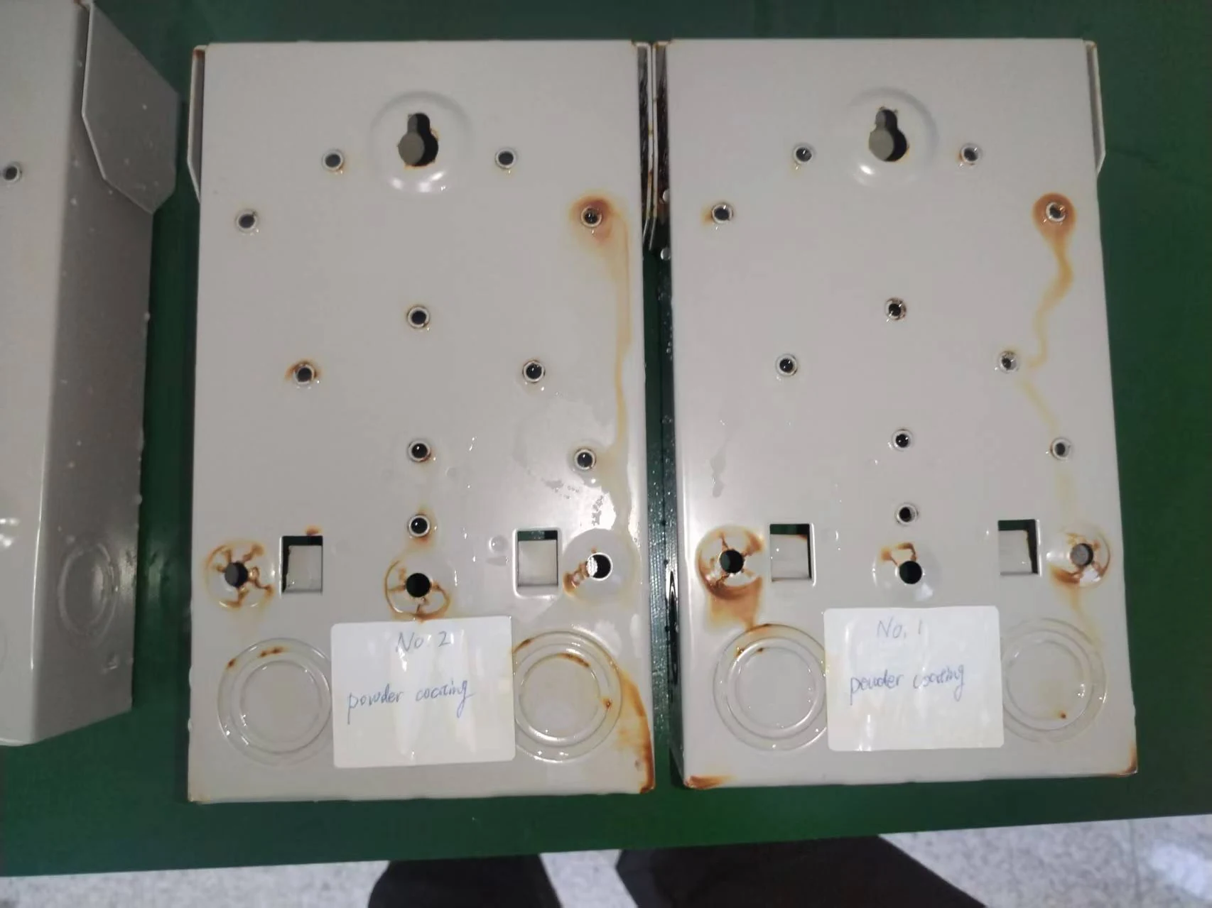
Samples A1 / A2 - Powder Coating Only
Sample A1 and Sample A2
Powder Coating Only
Observation
Final observation details will be added after the corresponding test image is reviewed.
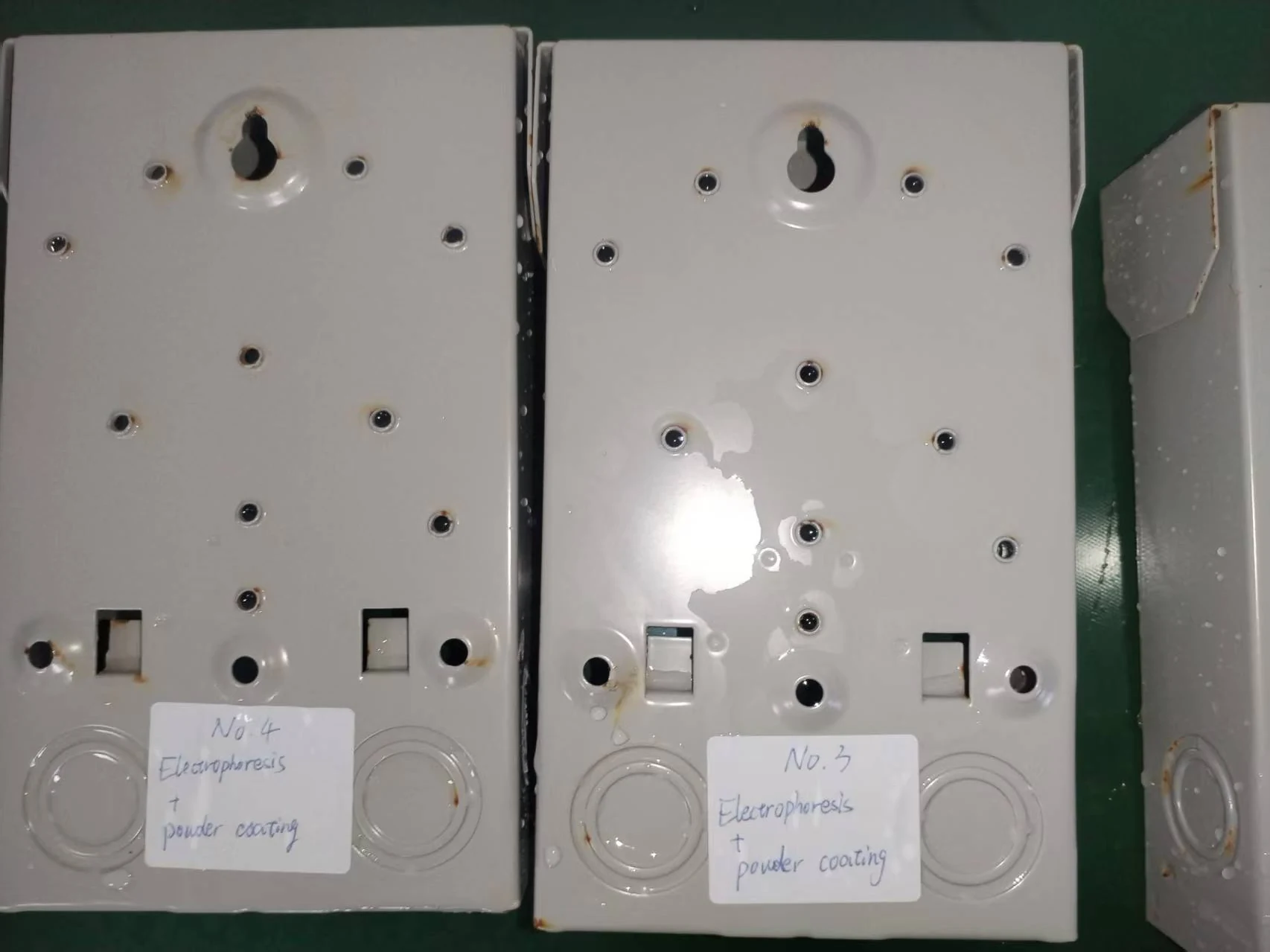
Samples B1 / B2 - Electrophoretic Coating + Powder Coating
Sample B1 and Sample B2
Electrophoretic Coating + Powder Coating
Observation
Final observation details will be added after the corresponding test image is reviewed.
Final Comparison Summary
This table is prepared as a concise engineering review format for the neutral salt spray test. Final corrosion observations will be completed after detailed image verification.
| Sample | Coating System | First Visible Corrosion | Primary Corrosion Area | Overall Observation |
|---|---|---|---|---|
| Sample No.1 | Powder Coating Only | Visible by 163 hours | Mounting holes, lower openings and bottom edge | Visible red rust developed around several exposed openings and became more pronounced by 243 hours. |
| Sample No.2 | Powder Coating Only | Visible by 163 hours | Mounting holes, knockout area and bottom edge | Rust appeared around multiple openings and spread further during the continued salt spray exposure. |
| Sample No.3 | Electrophoretic Coating + Powder Coating | No obvious red rust through 243 hours | No primary corrosion area identified | The coating surface remained visually stable with no obvious red rust during the documented test period. |
| Sample No.4 | Electrophoretic Coating + Powder Coating | No obvious red rust through 243 hours | No primary corrosion area identified | The coating surface remained visually stable with no obvious red rust during the documented test period. |
Side-by-Side Timeline Comparison
The timeline below is designed to compare each protective coating system at three stages: before testing, after 163 hours and after 243 hours.
Powder Coating Only
Before Test
163 Hours
243 Hours
Electrophoretic Coating + Powder Coating
Before Test
163 Hours
243 Hours
Key Observations
Coating Surface
Final observation will be completed after image verification.
- Surface appearance will be compared between both protective coating systems.
- Changes in gloss, blistering or discoloration will be documented.
- Visible surface changes on each AC disconnect enclosure sample will be recorded.
Supporting image annotations can be added after final review.
Edges and Corners
Edge areas will be reviewed because coating coverage can vary around formed steel parts.
- Corner coverage and edge corrosion will be checked against the final inspection photos.
- Any localized rust initiation around bends or cut edges will be noted.
- Observations will remain image-based until final engineering review is complete.
Supporting image annotations can be added after final review.
Screw Holes and Openings
Punched openings and screw holes will be reviewed as common stress points on steel electrical enclosures.
- Visible corrosion near punched holes, knockouts and mounting points will be compared.
- The review will check whether corrosion remains localized or spreads from exposed areas.
- Future annotations may identify specific openings in the supporting images.
Supporting image annotations can be added after final review.
Corrosion Development Over Time
The 163-hour and 243-hour images will be used to compare the timeline of visible corrosion resistance.
- The review will compare each sample before testing, at 163 hours and at 243 hours.
- Corrosion development will be described without overstating the accelerated corrosion test results.
- Final notes will distinguish confirmed visual evidence from pending interpretation.
Supporting image annotations can be added after final review.
Important Note
Visible appearance is only one part of coating evaluation. This internal comparison did not include adhesion testing, scribe creep measurement, coating thickness correlation or destructive examination after salt spray exposure.
What the Results Mean
This comparison is intended to show how two coating systems behave under the same accelerated salt spray exposure conditions. Once all images are reviewed, the final analysis will focus on where corrosion first appeared, how quickly it developed and whether the electrophoretic coating base layer provided additional protection in vulnerable areas.
The most important comparison is not simply whether rust was present. The location, timing and rate of corrosion development are also relevant when assessing the performance of a coating system.
Path B: Electrophoretic Coating + Powder Coating
Test Scope and Limitations
This test was conducted by Daheng Electric as an internal comparative evaluation. It was not performed or certified by an independent third-party laboratory.
The test conditions were based on neutral salt spray principles commonly associated with ASTM B117. This article should not be interpreted as a formal ASTM certification report.
Actual corrosion performance may vary depending on steel quality, surface preparation, coating thickness, curing conditions, scratches, installation environment, humidity, pollutants, coastal exposure and maintenance.
Salt spray exposure is useful for controlled comparison, but it does not reproduce every condition encountered during long-term outdoor service.
Continuing to Improve Through Testing
Daheng Electric uses internal testing to better understand how materials, surface treatment and manufacturing processes influence the durability of AC disconnect enclosures.
The purpose of this test is not only to present a final result, but also to document the testing process, compare coating systems and support future process improvement.
Looking for an AC Disconnect Manufacturing Partner?
We support OEM and private-label AC disconnect projects for North American customers, including enclosure manufacturing, logo stamping, labeling, packaging and quality inspection.